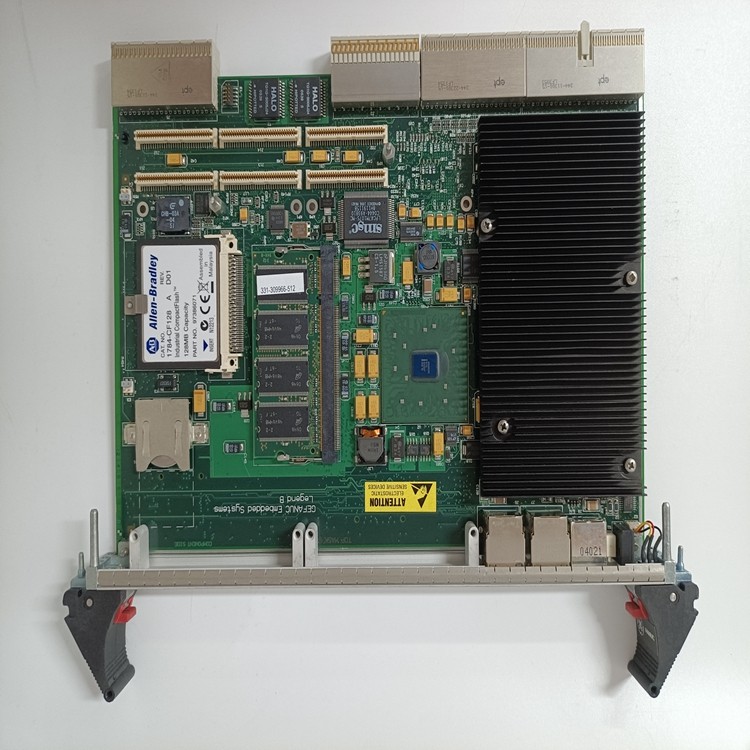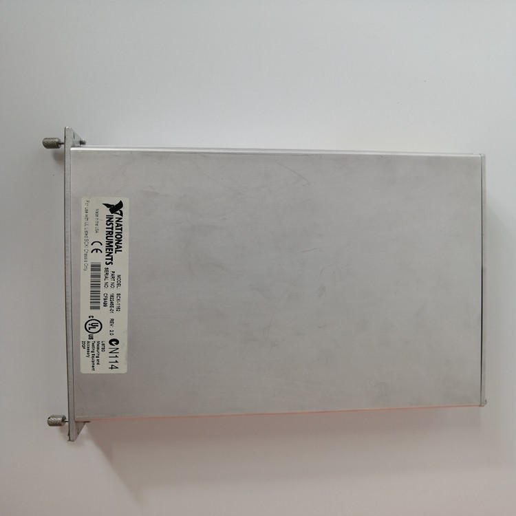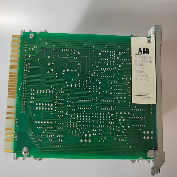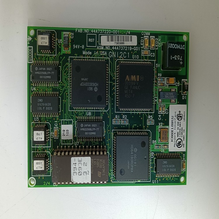


以太网和通信模块好货推荐
厦门雄霸电子商务有限公司
本店由供应网运营支持
参数规格
| 电压 | 60 | 电流 | 60 |
| 体积 | 0.6 | 重量 | 1.2 |
| 颜色 | 1 |
产品介绍


4 计算机控制系统的软件功能
计算机软件是以WIN2000为平台,采用组态软件WINCC实现以下功能。
3.1 信号处理功能
实现对数字量的输入,输出和模拟量的输入,输出的处理。
3.2 控制功能
实现各设备的顺序逻辑控制,对系统的选择,切换,起点,终点的确定及对系统的运行进行控制和管理。
3.3 其他功能
料仓监视功能:对料仓料满状态监视。
控制级由西门子的S7 - 300系列PLC控制器
构成,设有一主一从两个站,其中除尘地面站为主站,筛焦站为从站,每站配一个CPU,共设有五机架,硬件配置如图l所示:其中主站有三个机架筛焦从站设两个机架。主站配有CPU模块,I/O接口模块,电源模块,12个数字量输入模块,4个数字量输出模块,3个模拟量输入模块,1个模拟量输出模块。操作站工控机有两台,两台工控机之间和两个CPU之间通过通讯电缆连接,打印机用来打印报表和报警。操作站设于筛焦中控室,以便于集中控制。CRT画面显示功能:实现生产过程流程画面,操作画面,设定,报警等画面。
通信功能:实现与上位机,PLC之间的通信。
打印功能:打印报表,报警。
报警功能:设定优先级,实现事故报警。
4 除尘系统PLC编程
按照功能分类的思想,将程序分为四个部分。
4.1 系统启动
由于除尘只有一种方式,只须按工艺流程,实现设备的循环启动。在启动之前,首先判断模拟量条件和启动三条件是否满足,是则发出启动指令。因为偶合器是模拟量控制的,因此在程序中采用直接输出模拟量的方法去调节风机转速,根据需要标定高,中,低三档转速。一旦调好转速,则输出的模拟量不再改变。在出焦过程中风机处于高速,装煤过程中风机处于中速,其余时候风机处于低速。流程如图3所示。
4.2 集中停止
正常手动停止或某些轻度故障自动停机的方式。先停主风机,经过一段时间后,停脉冲控制仪,仓壁震动器,排灰阀,刮板运输机。当所有设备处于停止状态时,系统就处于停止状态。此时应注意将偶合器降至低位,关闭主风机人口阀,打开非常阀,作为下一次系统启动的三个先决条件。
4.3 一起停止
紧急手动停止或某些重故障自动停机的方式。当系统出现紧急状况时,采用此种停止方式,可以很快使系统处于停止状态。
4.4 模拟量处理
由于除尘系统存在大量模拟量,且模拟量要不论系统启动与否一直处于监视状态,因此单独划为一块。偶合器的位置判断也在此功能中。the way of equipment network field bus under the equipment network adapter hanging in the SLC500 controller. ? All electrical equipment status display, fault alarm, start and stop operation, and data modification are centralized in the upper computer ? A single electric drive equipment operation mode is set to three states: Machine side, maintenance, centralized. The different operation modes are determined by the switch of the operation box beside the machine. The equipment can not be started anywhere while it is under repair. The parking function can work in any way. When the device is set to work in a machine-side mode, the device is in an unlocked position. Therefore, the machine side working mode is used for the test run after the equipment overhaul, and the equipment should be in the centralized working mode during the normal production. The starting and stopping of the device, the control interlock logic, the electric program instructions and the alarm function of some devices are stored in the lower controller. 3.1.3 computer control system the computer control system is mainly divided into two major functional blocks: one is the upper computer system. Mainly man-machine interface. The other is the lower controller. It's mostly the control program. Through the man-machine operation screen to achieve people (production operators) and on-site equipment contact. All production equipment status and data in the upper computer in the agreed manner real-time display. The operator synchronously transmits the operation instruction and the modified data to the lower controller through the upper computer. Figure 3.1.3 shows the operation of the agitator tank feed adjustment. 3.1.4 equipment network field bus field operation box, frequency converter and other equipment in the form of field bus. Connected to the network of devices by a single wire, all data and signals are communicated by the network. The equipment of the equipment network is hung on the SLC500 controller under the 1747-SDN adapter, the network medium is thick cable, the transmission distance is 500 meters, the transmission rate is greater than 125KB. The field intelligent operation box realizes the up and down transmission of the switching data through a BLOCK/IO module with 1747-8B8P. The inverter can realize up-down two-way transmission including switching and analog signals (including device status, start-stop drive, running current, working frequency, etc.) through the optional GM5 communication card. 3.2 The man-machine conversation in the actual production is realized by the RSVIEW monitor configuration software in the upper computer. The entire production process flow diagram is shown in figure 3.2. The data display of conventional instrument panel and the display operation of electric operation table are all realized by the way of image and visual graph of the upper computer and the click of computer mouse. Figure 3.2 shows the start and stop screen of the 1 # Belt
联系方式
店铺好货推荐
发送询价单


 立即询价
立即询价
 进入店铺
进入店铺
 更多详情
更多详情